I've always wanted a low cost way to program PICs and a tablet seemed like a great solution. But most tablets either didn't have a USB port for the programmer or ran an operating system that didn't support the software tools I like to use such as Great Cow Basic and PICkit 2 software. Then I found the Winbook tablets at Microcenter. They offer a very low cost tablet that runs a full version of Windows 8.1 and has as full size USB port. On the smaller ones they are a USB 2.0 and on the larger versions they offer USB 3.0. 
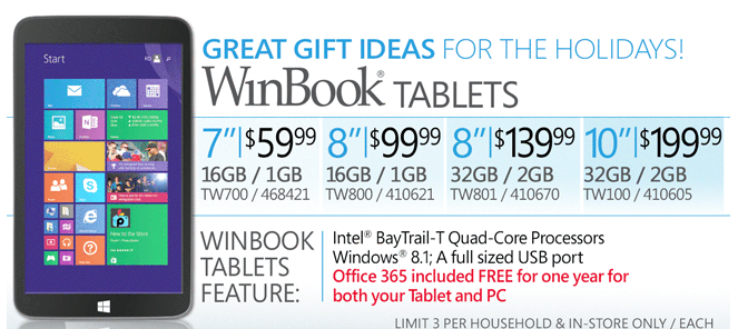
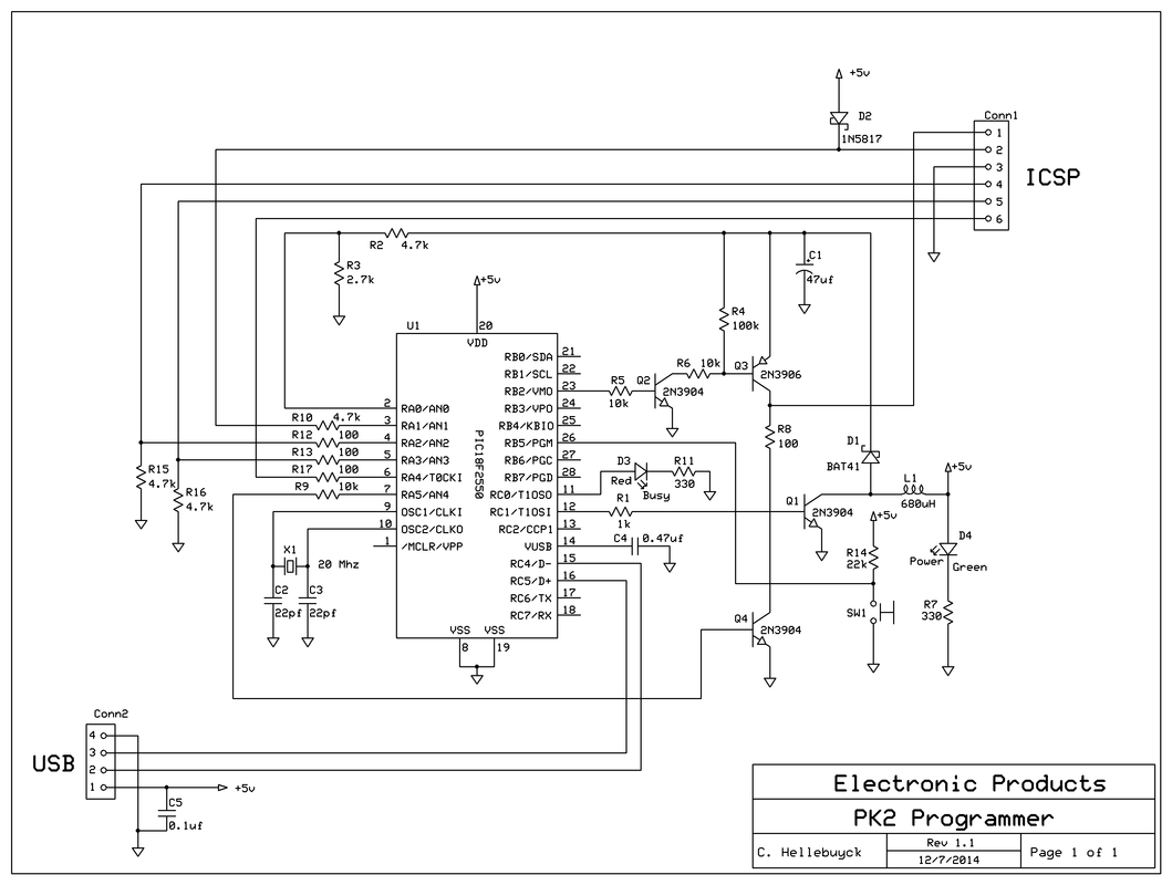
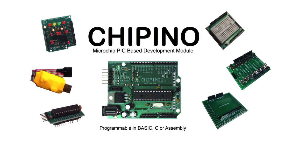
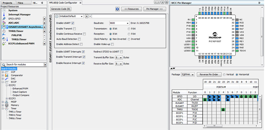
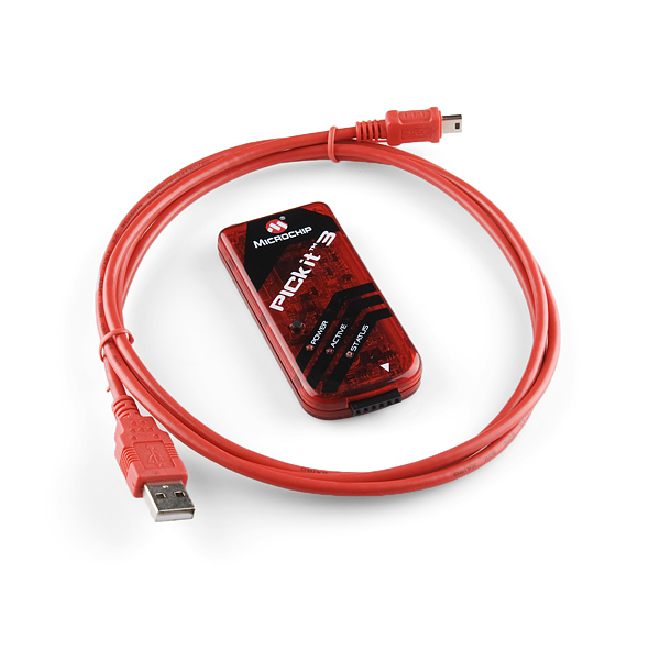
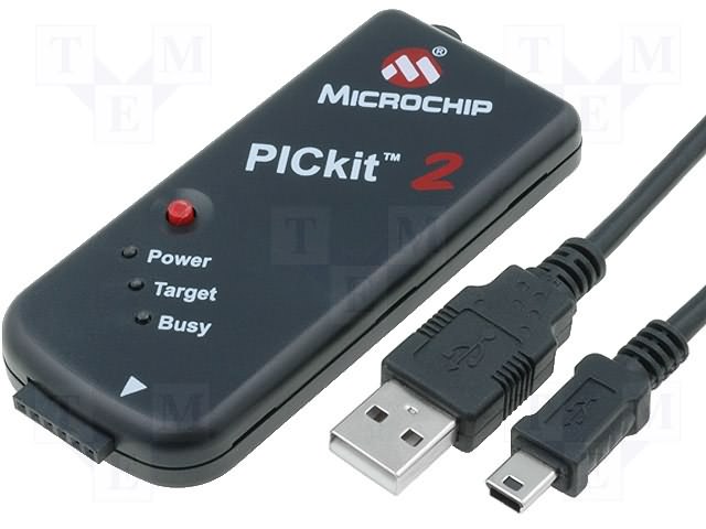
The pre-Christmas deals offered the smallest 7" Winbook for $59.95. It included Windows 8.1, 16GB of Flash Storage and 1GB of RAM. It also has wireless-N and a micro-HDMI port. So I bought one and downloaded the Great Cow Basic IDE at my Greatcowbasic.com site. I then ran the software without issue. The next step was to test the PICkit 2 on the USB port. This worked smoothly as the GCB IDE has the PICkit 2 command line interface built in. The programmer launched and programmed a PIC16F886 on a CHIPINO module without issue. I did find that 8GB of the 16GB was taken up by the operating system and other features so the memory size is limited, but plenty for what I was doing, at least I thought so. Then I decided to see if the Davinci 3D printer software, XYZware, would run on it. I downloaded that and it ran fine. I could load a 3D print into my Davinci without issues and the print was launched. My next step was to try and install the ExpressPCB software I like to use for creating circuit boards. Before I did that, I decided I needed a keyboard and mouse first. I tried a bluetooth keyboard but I couldn't it them to connect so I used a USB expander and was able to connect the PICkit 2, USB Keyboard and USB mouse to the tablet and everything worked great. I also wanted to to see if I could load Chrome on the tablet so I could modify Tinkercad designs but I found the memory usage was already getting low. Seems that Windows did an update and used up a bunch of space. I have to figure out what I can do to get some of that back but my idea of installing ExpressPCB may not be possible either. I guess 16GB isn't enough space. The 32GB is $139.95 but as the price gets higher I may just stick with a low cost laptop. The tablet has a microSD card slot so I'm going to try and load the programs on there and see if I can run everything from the SD card. So I've achieved one goal of programming PICs with a tablet but to create designs, write the software, send the 3D print file for a complete design from a tablet will require more memory with the SD card if that works or spend more money on a larger tablet which is not what I want to do. But at least I know its possible at the simplest of all levels. I can write a Great Cow Basic program and program a CHIPINO module with the code. Not bad at all for $59.95.
1 Comment
A reader of this blog, Frans Stevens, pointed out that the schematic for my Build Your Own PICkit 2 schematic had an error. The USB connections to D+ and D- were backward. I quickly looked over the schematic and also the PCB layout because I've built many of these and they all worked. But I found out he was right, the schematic was wrong. Luckily the PCB was correct and that is why all my PK2 programmers work fine. Pin 2 of the USB needs to connect to D- and pin 3 needs to connect to D+. I had them backwards in the schematic. So I immediately updated the schematic and uploaded to the Build Your Own PICkit 2 page. Its awesome to have such supportive readers with the willingness to share any errors they find. I want my information to be accurate but I'm human and do make mistakes. Thanks Frans. I recently donated some of my shield files to the CHIPINO.com website. They are just files from my kickstarter projects that I was sharing anyway but this way the CHIPINO team or anybody looking for CHIPINO support shields can get them at one location. I helped create the CHIPINO with a group of friends because I wanted to see a Microchip PIC based option to easily use the various Arduino shields. From there CHIPINO has grown on its own. The desire to make CHIPINO completely open source and not just the current non-commercial version is still something I'm pushing for. It worked out great for Arduino though maybe not the Arduino creators. The Arduino kind of took on a life of it's own and the originators kind of lost control. That is the scary part for some of the CHIPINO team. Because CHIPINO was designed to work with a Programmer, and not a bootloader, it allows CHIPINO to use any 28 pin PIC16F or 18F device that operates at 5v. That offers a lot of options. This also made the CHIPINO automatically grow with all the advancements in the Microchip PIC world. Programming a CHIPINO from a PICkit 2 or PICkit 3 with MPLAB or MPLAB X or any third party IDE and any compiler that produces a .hex file for PICs is possible with the current setup and thus makes it universal for developers of all types. From hobbyist to professional. It's one of the advantages I see to the CHIPINO has over Arduino which locks you into a crude IDE and only a couple chip options. But its clear that Arduino has taken over the electronics world so I'm clearly in the minority. But that is why I'd like to see the complete open source so others can take CHIPINO further. Time will tell. I'm also looking at changing my shield designs to completely open source as well (remove the non-commercial portion) as soon as the agreement I have with Howtronics.com expires.
I have other designs to clear out of my lab which I'll be releasing open source over time. Each will probably be a project on my YouTube Channel. I have just so many designs I've worked on over the years and its time I just let them go for others to fully enjoy and possibly take them further than I ever could. I've been planning a series of videos for my various books and I decided to start with my Programming PICs in BASIC book. This book has been very popular but I do get a lot of questions from beginners. So today I launched the first in a series of videos based on this book. In this one I show you how to setup the software and hardware to get that first project running. The typical blink LED is used as the test project, but when this works that means you have the compiler working, the programmer working and the hardware circuit built properly. That is actually a lot to cover and can be the biggest hurdle for a beginner. Sometimes it helps just to see the steps rather than rely on the description in a book so I put this video together. I used the Large IC breadboard box 3D print to hold the circuit which was a previous video on my channel. The intent is to show how to get started and then I'll follow this up with a video for each chapter in the book in the future. Then I'll tackle my Beginner's Guide to Embedded C series of books after that. I hope you enjoy this one. I've been doing a lot of 3D printing lately but in the background I'm working on new books. One of them is an update to my Beginner's Guide to Embedded C Programming series. In the first series, I used MPLAB, HI-TECH C Compiler, PICkit 2 programmer and a PIC16F690. All those have been replaced. MPLAB X, XC8 Compiler, PICkit 3 programmer and the PIC16F1xxx family of enhanced mid-range devices. Something else changed recently which has me delaying my book, MPLAB Code Configurator (MCC). MCC was in beta for a while but is now released and already on version 2.1, and it is awesome. With a few clicks of the mouse you can build a whole project of code (see it in the video below). Each peripheral is reduced to a set of check boxes or drop down menus. I/O can be configured with a GUI version of the chip. Even the main.c file can be generated. And the best part..... .....all the code generated includes a library of functions for each peripheral written in XC8 code. Even I/O has its own set of functions such as: RB0_SetHigh() RB0_SetLow() RB0_Toggle() RB0_GetValue() RB0_SetDigitalInput() RB0_SetDigitalOutput() RB0_SetPullup() RB0_ResetPullup() RB0_SetAnalogMode() RB0_SetDigitalMode() And these are just the I/O functions for the RB0 pin. And the function code is open source so you can see how its done. Great for learning. It does the same for SPI, I2C, Timers, etc. You could take a module like the CHIPINO with fixed pinouts, install a PIC16F1936 (instead of PIC16F886), setup all the peripherals and connections to the I/O and then build the code. You'll have a main.c file with configurations set and ready for your custom code along with a library of functions for all the peripherals in the device.
You basically just created your own Arduino style module from a CHIPINO. And you have debug capability through the PICkit 3, full access to the configuration to run slower speeds or faster speeds. And when you are done, unplug the PIC16F1936 and do it again for some other blank 28 pin PIC with different features. And because you don't need a custom bootloader device, you can use any PIC supported by MCC. And that list is growing with each release. So stay tuned for more as I work this into my new series of books. Writing C code for PICs just got so easy. I cannot say that enough. I released a new video on my YouTube channel for those setting up a home lab and who may want a little help choosing a PIC Programmer. I actually go back to the first hobbyist PIC programmer called the PICSTART 16B1 and then take the viewer through some of the most popular PIC programmers in history to get us to where we are today. By no means did I cover every design, just the highlights from my years of experience. There are still many designs out there so it can be confusing but in the end I recommend sticking with the official PICkit programmers, though building your own like my PK2 is fun and you can learn a lot. The video is short but hopefully viewers like it enough to subscribe and let me know they are watching and hoping for more. I plan to release future videos in three categories; 3D print projects, beginner electronic projects and tips for the home lab. Check it out and let me know your ideas for what you'd like to see in a future video. The final print of my PK2 case using my new Davinci 3D printer worked good. I now have a stack of failures in my lab to get to this point but many of them were my own mistakes. I used TinkerCad for the design. I did a final print of the cover at 0.1 height and 90% fill. I didn't have a lot of success with this in previous prints but this time it came out good. I've found that the placement of the design on the heated bed affects the results. Since the top of the box is the bottom of the print, the heated bed had a huge affect. The side snaps needed a little trimming with an Exacto knife to get rid of the extra plastic, but that was expected as I didn't design in any support for the over-hanging wedge on the top walls. The plastic sags without support and then cools off in that sag position. A simple slice with the Exacto cleaned it up. I gave up on putting the elproducts.com name on the case top because it was unreadable. I even tried it as a cutout like the PK2 but it needed to be too big for the Davinci to print it readable. The case makes a nice package if you don't want to use a bare board design. I'm going to add the .stl files to my PICkit 2 page so anybody can print them. This makes a nice project for an electronics class. Build the board and then print the case. In the end you have a useful project. Use it with the free Great Cow Basic compiler and you can be programing PICs in no time.
Note: The Davinci 3D printer went is now $529 vs the original $499 at Amazon.com. Demand drove it up apparently. And they are out of stock again. I'm told that MicroCenter will carry them so if you have one of those stores near you check it out. If you buy one through the link in the upper right on this blog, I get a small royalty so if you like what I write consider clicking there first. In my March 24th blog post I talked about ordering an updated version of my PICkit 2 clone board from ITEAD studios back on March 13th. On March 18th I was emailed that they were shipped. By my blog post the boards were still in transit. They arrived today on the 28th so I can compare them to the originals from ExpressPCB. 10 days for shipping via air mail wasn't too bad. I haven't built one up yet but I am impressed with the quality of the board. In the picture above you can see the ITEAD board on the left and the original ExpressPCB board on the right. First thing to notice is the shape. To get the low cost $85 for three prototype board service from ExpressPCB I had to order in a 2.5 x 3.8 panel. I ended up squeezing in another board design to use up the extra space but it all required me to cut out the board. The ITEAD board was routed out for me for $20 and I have 10 of them instead of three. Next I looked at the silkscreen and the ITEAD is brighter and easier for my old eyes to read. The solder mask is a little brighter green as well but that really doesn't matter. The board is hot air solder leveled (HASL) on all the pads and they look real good and should be easy to solder.
I tested the mini B connector in the board and it fit fine. This was the major change to the board in addition to removing the power plane on top and replacing it with a 0.020" trace. So it looks like it will work but the real test will be when I solder it together and see if it can program a PIC. That will be the ultimate test. I'll update you on that in a future post. I've put together an explanation for Understanding Microchip PIC .hex files many times but when I need it I can't find it. I'm just not organized enough. That is a big part of the reason I've built this website. I now have an online place to store my notes about programming Microchip PICs and all my supporting projects right here in one place. So I put together a detailed summary of how to analyze and understand a .hex file once again and gave it its own page. Its on my site now for everyone to view. Check it out and let me know if this helps you in any way. I didn't want to make it too long like some summaries I've seen, but I think I covered the topic well enough to help you understand it. People who want to create their own bootloader for PICs will need to understand this file format so maybe someone will gain from this post. If you do find this post or any of my blog posts helpful, then help out this site by supporting our sponsors, or clicking on the ad below. I also have an Amazon store now with stuff I recommend. Purchase through my AStore and you pay the same price but Amazon sends me a small royalty. Thanks. I have another PK2 programmer update for you. My PK2 design just got a little better. I wanted to try out the new PIC16F1788 in a CHIPINO module because I noticed that Great Cow Basic Compiler supported it. But I quickly realized that the latest device file for PICkit 2 didn't support it. So it gave me reason to try out the Device File Manager by user name Dougy83. The device file manager is a great tool for updating the Device file for PICkit 2 (and my PK2). I used a PIC16F1784 which was supported and made a copy within the tool. Then I downloaded the PIC16F1788 programming spec to get all
|
Categories
All
Visit previous blog posts in the archives below.
Archives
February 2018
About ChuckChuck has been programming with PIC Microcontrollers since there were only five devices. Now there are over 700 and growing. He also has a lot of fun 3D printing designs using his Davinci 3D printer and TinkerCad software. In this series of blog posts and occasional videos on his YouTube Channel he tries to help you get started with electronics and 3D printing. Disclaimer |
- Books
- Chuck's Blog
- YouTube Channel
- About Chuck
- 3D Printing
- Getting Started with PICs
- Build Your Own PICKit 2
- CHIPINO
- CHIPAXE Breadboard Modules
- Understanding Hex Files
- chipKIT
- Newsletter Archive
- Contact
- Retired Designs
- Downloads
- Kickstarter Projects
- Great Cow Basic Site
- Buy Hardware
- Links I Recommend